3 Wire Control Circuit Diagram
Circuits divided Vfd wiring instructions Circuit control wire three start diagram motor button auxiliary industrial push seal contacts coil ladder connected
Ladder Diagram Basics #3 (2 Wire & 3 Wire Motor Control Circuit) - YouTube
Motor phase circuit control works Plc circuit ladder electrical motor control relay phase robotics electronics program above three Motor button stop start diagram wiring starter circuit relay retain 480v control wire 120v push switch electrical symbol phase limit
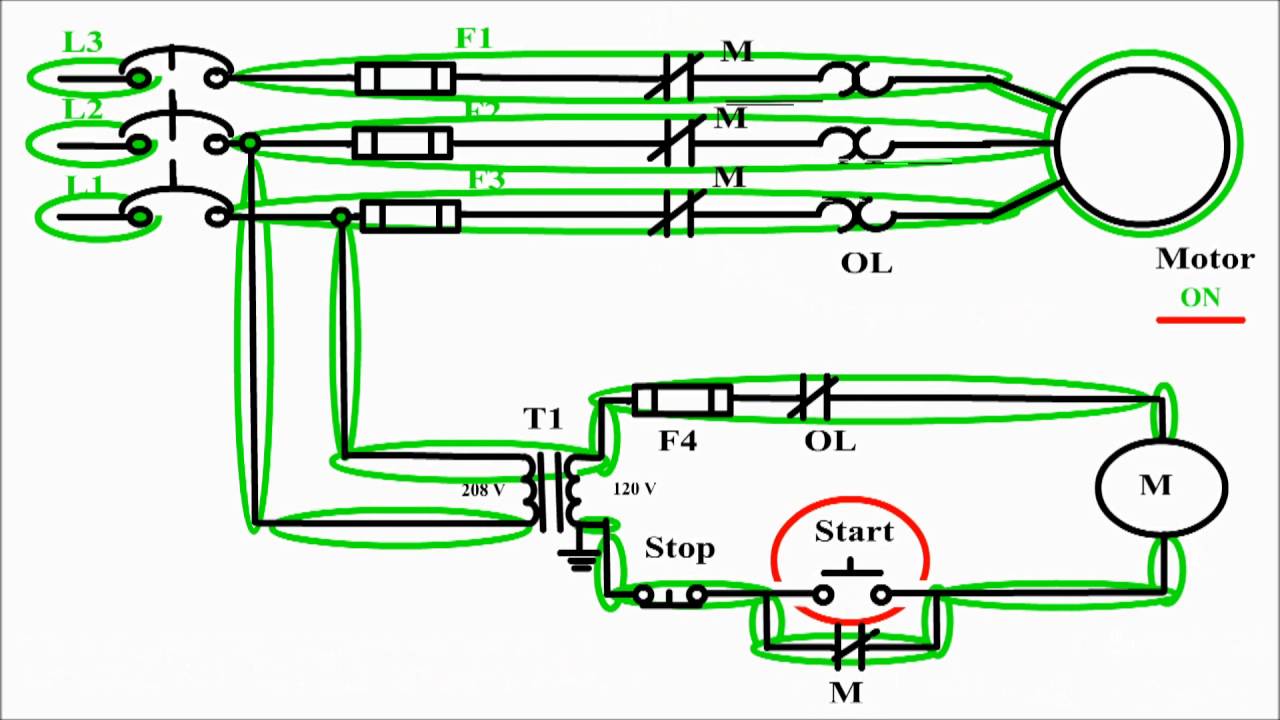
Motor control circuit diagram / start stop 3 wire control
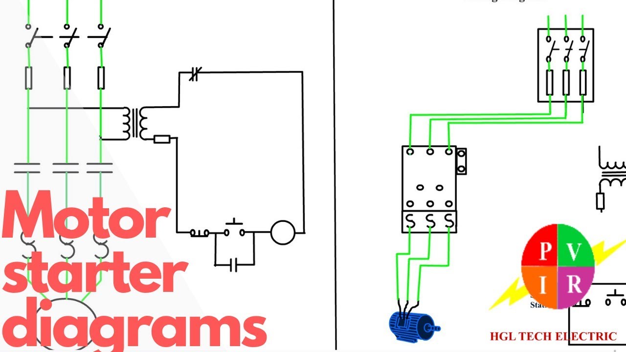
Motor starter diagram phase wiring start stop control wire circuit three starting 480v electrical reversing voltage holding electronic simple ac2 wire control circuit diagram. motor control basics. controlling three 3 wire motor controlMotor diagram control wiring circuit wire motors phase basics controlling diagrams three switch sponsored links.
Auxiliary reversing rockwell voltage latching diagrams contactor electric eletrical dol ghisalba rotate viz switches voltLadder diagram basics #3 (2 wire & 3 wire motor control circuit) Wire circuit two control motor diagram three configuration gif electricalMotor starter diagram. start stop 3 wire control. starting a three.

How a 3 phase motor control circuit works
3-wire controlWire motor control diagram circuit ladder basics Circuit control wire lamp three indicator motor wiring diagram ladder starter coil industrial when fig above energized added showMotor diagram control stop start circuit wire sponsored links.
Three-wire control circuit with indicator lampThree-wire control circuit Clear electronic project box: wiring diagram for 3 phase motorTwo wire & three wire motor control circuit.

Vfd wiring diagram probotix instructions huanyang wiki spindle wire board power speed controller 10v output 24v pixels original mill contact
Electrical electronics robotics: plc .
.

Motor control circuit diagram / start stop 3 wire control - YouTube

3 Wire Motor Control

Electrical Electronics Robotics: PLC

VFD Wiring Instructions - Add-ons & Modifications - Sienci Community Forum

Three-Wire Control Circuit with Indicator Lamp

Ladder Diagram Basics #3 (2 Wire & 3 Wire Motor Control Circuit) - YouTube

3-Wire Control - Start Stop Circuit
Motor Starter diagram. Start stop 3 wire control. Starting a three

2 Wire Control Circuit Diagram. Motor Control Basics. Controlling three